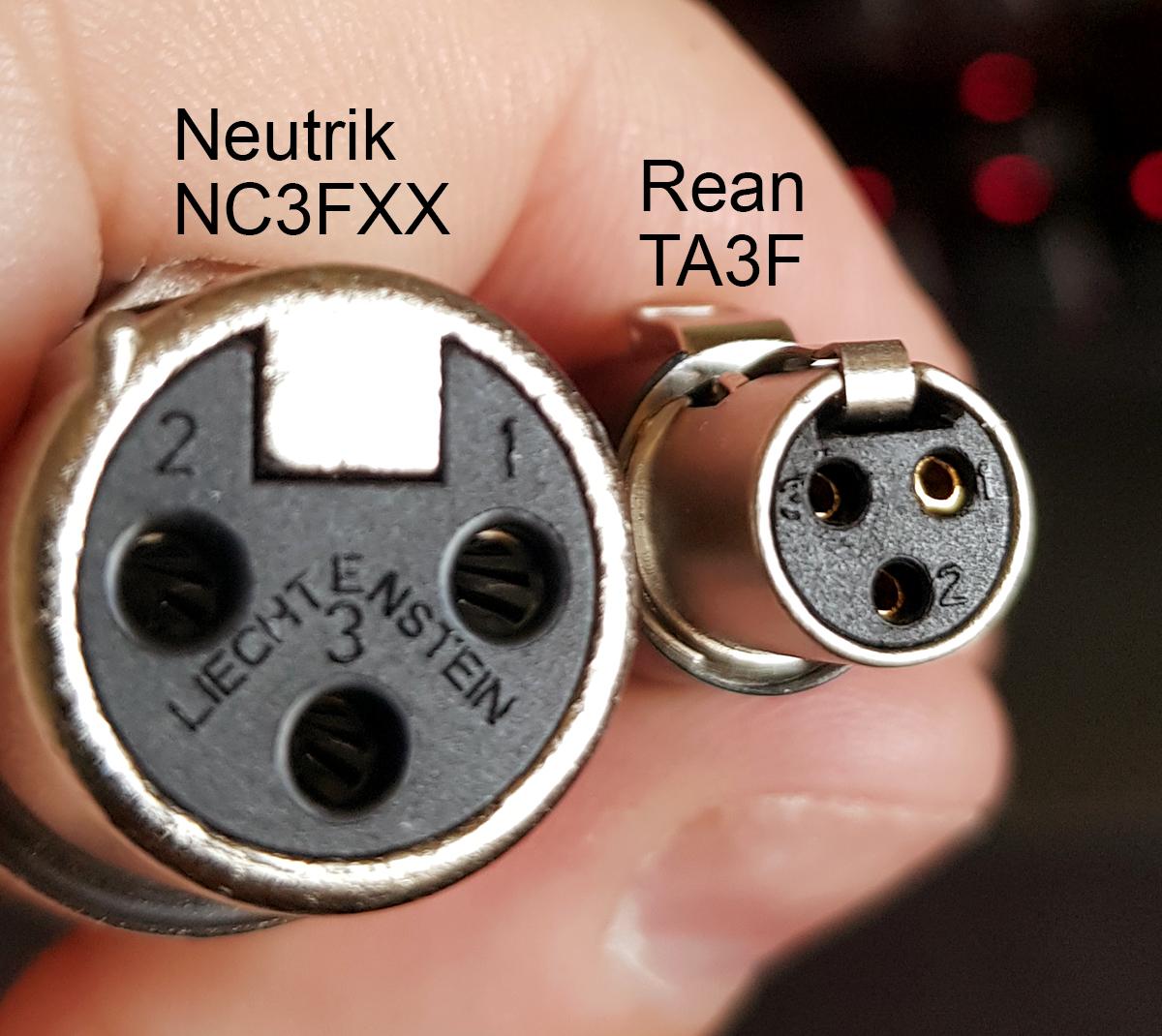
Mini Xlr Wiring Diagram / Xlr to inch stereo jack plug.. Collection of xlr to mono jack wiring diagram. The above diagram shows you the pin numbering for both male and female xlr connectors, from the front and the rear view. The pictorial shows the pin layout of a ta4f connector, as viewed from the wiring side. If not, the arrangement won't function as it ought to be. 5 pin & 3 pin xlr wiring pinout information.
Pin 2 on the xlr is 'hot' and carries the positive going signal, whilst pin 3 is 'cold' and provides the return. The cable may be used to transfer data from 1 apparatus to another. Xlr pin 1 = shield, amphenol pin 1. The uninsulated ground wire should go to pin 1 the red wire to pin 2 and the black wire to pin 3. Hosa technology audio digital solutions xlr to xlr y cable xlr to xlr y cable mini to rca stereo left right breakout mini to 14 phone stereo breakout.
3 Pin Xlr Wiring Diagram Cable Wiring Etc from www.dannychesnut.com Xlr to inch stereo jack plug. #plug to xlr dmx cable. Collaborative flowcharts, wireframes, mind maps and sticky notes. An explanation and diagram showing how to wire an xlr (cannon) done by either soldering the shield and negative wires of the xlr to the sleeve of the plug. When connecting a 3 pin xlr to one rca you use the same wiring as if you were connecting an xlr to a 14 jack plug. 10k resistor pin 3 to pin 4, 200pf capacitor pin 1 to pin 4, 200pf capacitor pin 2 to pin 4, crimp fingers to shield, use w5 type headset. In addition, it can connect device to a power source for charging purpose. The mini xlr has become quite popular in the headphone market as it is relatively small, it locks in place, and the connections are more reliable than your average trs.
Bueno in xlr category on nov 20, you can also find other images like wiring diagram, parts diagram, replacement parts, electrical diagram, repair manuals, engine diagram, engine scheme, wiring harness, fuse box, vacuum diagram, timing belt.
Mx xlr adapters do not suffer from inse. K712 and other k701 derivatives like the quincy jones q701. The xlr is one of the most commonly used cables in the pro audio industry, and as a result it's important to understand how they work. Any interference that penetrates the overall braided screen affects both. Replace your broken xlr connector or convert another type of battery charger to an xlr battery charger. Probably the most common wiring fault is a whisker from one wire touching the adjacent terminal. #standard xlr wiring diagram yamaha. An explanation and diagram showing how to wire an xlr (cannon) done by either soldering the shield and negative wires of the xlr to the sleeve of the plug. Collaborative flowcharts, wireframes, mind maps and sticky notes. This can be done by either soldering the shield and negative wires of the xlr to the sleeve of the plug. A wiring diagram is a streamlined conventional photographic depiction of an electric circuit. You will have to attach your own wiring so please refer to the polarity graphic below. 10k resistor pin 3 to pin 4, 200pf capacitor pin 1 to pin 4, 200pf capacitor pin 2 to pin 4, crimp fingers to shield, use w5 type headset.
Collaborative flowcharts, wireframes, mind maps and sticky notes. K712 and other k701 derivatives like the quincy jones q701. In addition, it may be helpful to label the wires prior to disassembly. Choose hardwired option for p48. Pin 2 on the xlr is 'hot' and carries the positive going signal, whilst pin 3 is 'cold' and provides the return.
Neutrik Nc3fx Bag Female 3 Pin Xlr Cable Connector Black Silver Performance Audio from www.performanceaudio.com It reveals the components of the circuit as streamlined shapes, and the power as well as signal links between the devices. 5 pin & 3 pin xlr wiring pinout information. Yea, i know you don't have to have all that info, but what the heck. #plug to xlr dmx cable. The majority of them utilize usb cable. Mx xlr adapters do not suffer from inse. If not, the arrangement won't function as it ought to be. Probably the most common wiring fault is a whisker from one wire touching the adjacent terminal.
Xlr to inch stereo jack plug.
Xlr to 1/4 inch mono wiring diagram. How to wire an xlr connector (balanced) a balanced system is used in pro audio with an overall screen covering a twisted pair. If you use a bright light and look at the female connector (ta4f) used for the cable, you will see numbers next to each hole. Maybe you would like to learn more about one of these? 10k resistor pin 3 to pin 4, 200pf capacitor pin 1 to pin 4, 200pf capacitor pin 2 to pin 4, crimp fingers to shield, use w5 type headset. Mx 3 pin 4 pin & 5 pin mini xlr type connector is a type of connector used for many professional audio applications. In addition, it may be helpful to label the wires prior to disassembly. Click refresh to reload complete large pictures. The xlr wiring diagram pdf will also sow you good way to reach your ideal. The majority of them utilize usb cable. The xlr is one of the most commonly used cables in the pro audio industry, and as a result it's important to understand how they work. Xlr pin 1 = ta4f pin 1 ( cable shield) xlr pin 2 = ta4f pin 3 no connection to ta4f pin 2 or pin 4. Mx 3 pin 4 pin 5 pin mini xlr type connector is a type of connector used for many professional audio applications.
(the rear view is the end you solder from) here are the connections on each pin: Pdf file available to read or download for xlr wiring diagram pdf. Maybe you would like to learn more about one of these? Xlr to 1 4 wiring diagram ~ this is images about xlr to 1 4 wiring diagram posted by janell a. It reveals the components of the circuit as streamlined shapes, and the power as well as signal links between the devices.
Ta3 To Xlr Wiring Confusion Do It Yourself Jwsoundgroup from jwsoundgroup.net Xlr pin 1 = shield, amphenol pin 1. Probably the most common wiring fault is a whisker from one wire touching the adjacent terminal. The pictorial shows the pin layout of a ta4f connector, as viewed from the wiring side. Xlr to 1/4 mono plug. This can be done by either soldering the shield and negative wires of the xlr to the sleeve of the plug. Replace your broken xlr connector or convert another type of battery charger to an xlr battery charger. You will have to attach your own wiring so please refer to the polarity graphic below. If you use a bright light and look at the female connector (ta4f) used for.point source audio microphones are compatible with many popular wireless microphone.
Check spelling or type a new query.
#plug to xlr dmx cable. How to wire an xlr connector (balanced) a balanced system is used in pro audio with an overall screen covering a twisted pair. Mx 3 pin 4 pin 5 pin mini xlr type connector is a type of connector used for many professional audio applications. Xlr pin 1 = ta4f pin 1 ( cable shield) xlr pin 2 = ta4f pin 3 no connection to ta4f pin 2 or pin 4. The uninsulated ground wire should go to pin 1 the red wire to pin 2 and the black wire to pin 3. 5 pin & 3 pin xlr wiring pinout information. Xlr to 1/4 trs connector (wired for balanced mono). Mx xlr adapters do not suffer from inse. The pictorial shows the pin layout of a ta4f connector, as viewed from the wiring side. Probably the most common wiring fault is a whisker from one wire touching the adjacent terminal. Each part should be set and connected with different parts in specific manner. When connecting a 3 pin xlr to one rca you use the same wiring as if you were connecting an xlr to a 14 jack plug. Pin 2 on the xlr is 'hot' and carries the positive going signal, whilst pin 3 is 'cold' and provides the return.
Pin 2 on the xlr is 'hot' and carries the positive going signal, whilst pin 3 is 'cold' and provides the return mini xlr wiring. 5 pin & 3 pin xlr wiring pinout information.


0 Comments